Introduction The bq2031 incorporates the necessary PWM control cir cuitry to support switch mode voltage and current regu lation as required by its charge control function block This application note describes how to configure the bq2031 in buck mode switching power supply topology A methodology for phase compensation of the voltage and current feedback loops is recommended A brief de scription of the PWM control circuitry and phase com pensation criteria appears below followed by a discussion dealing with topology specific issues
Texas Instruments, Incorporated
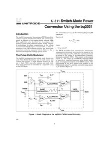
Niveau: Secondaire, Lycée, Terminale Introduction The bq2031 incorporates the necessary PWM control cir- cuitry to support switch-mode voltage and current regu- lation, as required by its charge control function block. This application note describes how to configure the bq2031 in buck mode switching power supply topology. A methodology for phase compensation of the voltage and current feedback loops is recommended. A brief de- scription of the PWM control circuitry and phase com- pensation criteria appears below, followed by a discussion dealing with topology-specific issues. The Pulse-Width Modulator The bq2031 incorporates two voltage mode direct duty cycle Pulse-Width Modulators, one for each control loop (voltage and current). A block diagram is shown in Fig- ure 1. Each PWM runs off a common saw-tooth wave- form whose time-base is controlled by a capacitor, CPWM on the TPWM pin. The relationship of CPWM to the switching frequency, FS is given by: Equation 1 F C kHzS PWM = 0 1. where: CPWM is in µF. The PWM for either loop consists of a comparator whose positive terminal is driven by the output of the sawtooth ramp signal, VS, while the negative terminal is driven by the output of an Operational Transcon- ductance Amplifier (OTA). The output is the control signal, VC. The output of each PWM is logically ORed to generate a constant frequency pulse width modu- lated rectangular waveform at the MOD output.
- pwm transfer
- only func- tion
- characteristics can
- loop
- pwm control
- db gain
- during voltage
- output power
- voltage control
- function